TORQUETRAK 10K FAQ
FREQUENTLY ASKED QUESTIONS
What should I consider while installing the system?
The three components that must be installed on the shaft – strain gage, Transmitter and 9V battery (inside the battery holder.) These same three items are used on any size shaft, large or small. The only limitation is on very small shafts, less than 0.5” diameter, for example, where a smaller strain gage may be required. The strain gage – standard full-bridge torque pattern – is approximately one square inch in size. (For details and instructions, please see Full-Bridge Strain Gage Installation Instructions & Diagram and Training Videos.) The Transmitter is nearly the exact same size, shape and weight as the 9V battery plus battery holder. Balance is not usually an issue, except maybe on smaller shafts – less than 1 inch in diameter, for example. You can roughly balance the components simply by installing them approximately 180 degrees opposite each other.
The Receiver should be located within 6 feet of the Transmitter. (Actual transmission distance may be much greater.)
The Transmitter and battery holder have a groove for the fiberglass reinforced strapping tape, which should be wrapped around at least ten turns to secure the components to the shaft. The open end of the tape should follow shaft rotation, rather than lead shaft rotation. For extra protection, glue the end of the tape down so that it cannot unravel. When finished with your testing, cut the tape and remove the components.
What is system accuracy and how is it calibrated?
Using the TorqueTrak 10K telemetry system, you can achieve Accuracy better than ±1.0% Full Scale. Accuracy is a function of two primary elements – proper installation of the strain gage and accurate determination of the “Sensitivity” of the system. The entire “system” includes the shaft, the strain gage and the TorqueTrak 10K. “Sensitivity” is expressed in terms of Torque-Input per Voltage-Output. The Input-Output curve is linear, so you only need one point of reference. Shown below are three methods of determining “Sensitivity.”
1. The most precise method for determining Sensitivity of the system is a true mechanical calibration, sometimes called a Deadweight Test, where a known torque (a known force/weight on a known moment-arm) is applied to the shaft and the corresponding output signal is recorded. Example: 100 pounds weight on a 1-foot moment-arm equals 100 foot-pounds “known Torque-Input.” Apply the known torque and observe the Voltage-Output of the TorqueTrak 10K system. Sensitivity of the entire system is equal to the Torque-Input per Voltage-Output. Take two or more points of reference using different known Torque-Input values as confirmation of the “Sensitivity” value.
The known moment arm should be affixed to the shaft using a clamp or perhaps by bolting onto a flange. The length of the moment arm should be measured accurately from the axis of the shaft to the point of applied force/weight. The known force/weight could be calibrated weights free-hanging from the arm, in which case the moment arm would be the horizontal dimension. Or the known force could be applied using a calibrated torque wrench. On large shafts the known force could be applied using a crane or a jack and measured with a calibrated load cell.
Be Careful! The applied force and the moment arm must be perpendicular to each other. Be careful with your measurements, especially if the moment arm drops when free hanging weight is applied. In this case, the length of the moment arm becomes shorter in the dimension perpendicular to the weight/force.
2. Full Scale Torque Calculator: TorqueTrak 10K – Range Calculator
This is the most common method of determining Sensitivity. The upper calculator on this page can be used to determine the best GAIN setting for the TorqueTrak 10K, based on shaft characteristics and the amount of torque you expect to apply to the shaft. (Standard factory default: GAIN = 4000.) For best accuracy, enter precise values* for all the inputs – Shaft Diameter, Gage Factor, Modulus of Elasticity and Poisson Ratio. Then, “Calculate Full Scale Torque.” The resultant Full Scale Torque relates exactly to the Full Scale Output Voltage, 10.0 VDC, of the TorqueTrak 10K. Sensitivity of the entire system is equal to Full Scale Torque-Input per Full Scale Voltage-Output.
* Shaft Diameter has a major influence in the Sensitivity calculation – a precise value should be used. Gage Factor is supplied with the package of strain gages. Modulus of Elasticity and Poisson Ratio were probably recorded by the shaft manufacturer, but it may be difficult to recover those values. Using nominal values for Modulus of Elasticity and Poisson Ratio introduces an uncertainty of perhaps ±3% of the torque reading. This is not to say that using nominal values introduces error, because the true shaft characteristics may be exactly equal to the nominal values used.
3. Torque/Strain Calculator plus Shunt Resistor Calculator: calculator The upper calculator on this page can be used to determine the strain in units of “microstrain” (microinches/inch) that results from a given torque on a defined shaft (diameter, etc.) Knowing the expected full scale “strain” in your application will be useful when selecting a GAIN level for the TorqueTrak 10K telemetry system. The lower calculator can be used to determine the shunt resistance value that relates to the known strain/torque determined in the upper calculator. Apply the shunt resistor to the strain gage bridge to simulate the known Torque-Input. Observe the Voltage-Output of the TorqueTrak 10K. Sensitivity of the system is equal to the Torque-Input per Voltage-Output.
The strain gage is a resistive full bridge configuration. With standard wiring, applying the shunt resistor between the nodes (+EXC and +SEN) or (–EXC and –SEN) will cause the output signal to move in the positive direction. Changing the polarity of one of the nodes (changing from +EXC to –EXC, for example) will cause the output signal to move in the opposite direction.
4. The TorqueTrak 10K has two reference shunt calibration resistors built into the Transmitter that can be applied using the Remote Control. These are real shunt resistors applied right at the strain gage to simulate real strain.
Shunt resistor (Reference 1): 437400 Ω, +/-0.1 %, 25 ppm/°C. Simulated strain*: 100 microstrain, nominal. Shunt resistor (Reference 2): 87370 Ω, +/-0.1 %, 25 ppm/°C. Simulated strain*: 500 microstrain, nominal. * Simulated strain values assume 350 ohm full-bridge strain gage.
Frequency Response: 0-500Hz (-3dB @ 500Hz).
Sampling Rate: 2400 samples/second.
Step Response (Delay plus Rise Time), Torque Input: 4.2msec, typical.
Filter: The Filter parameter allows the user to change the bandwidth of the output signal. It functions as a low pass filter, meaning frequencies above the selected value are attenuated. This allows the user to reduce the amount of high frequency data on the output signal (i.e., reduce noise) and effectively average the output value. Selectable filter values are 500, 250, 120, 60, 30, 15, 8, 4, 1 Hz.
How do the channels work?
A channel is a single data transmission signal from a single sensor, usually a strain gage bonded to the shaft. The TorqueTrak 10K has sixteen available channels. For each channel, the data is “broadcast” by the TX10K Transmitter using a different, unique radio frequency. All sixteen channels are in the broadcast frequency band of 903 to 925 MHz. Each channel (each data signal) requires a complete TorqueTrak 10K system, Transmitter plus Receiver. The RX10K Receiver can process only one data signal at a time – it has only one output signal. For example, to process two data signals simultaneously, you will need two complete TorqueTrak 10K systems – two Transmitters and two Receivers – each system set to a different channel. Because the two systems would be set to different channels, the transmitted data signals will not interfere with each other – no “crosstalk.”
It is possible to use several TX10K Transmitters with just one RX10K Receiver, if you are willing to “toggle” from one channel to the next. For example, you could have two Transmitters broadcasting their data signal simultaneously. Using only one Receiver, you could process channel #1 for some period of time, then change to channel #2 using the Receiver keypad. Still, you can only process one channel at a time. But you can change from channel #1 to channel #2 and so on without having to stop the equipment. Please consider the differences per sensor (per channel) when using one Receiver to “toggle” multiple Strain Gage/Transmitter channels. Specifically, the Zero Offset and the Transmitter Gain setting may not be the same for all channels. If you are not able to stop the equipment in order to AutoZero and recalibrate as you toggle to each new channel, you may want to make the various Strain Gage/Transmitter channels equivalent beforehand. For example, you could “balance the bridge” for all channels, making all the initial null offsets equal to Zero by installing shunt resistors as necessary right at the strain gages or at the screw terminals of the Transmitter. Make sure the various Transmitters are all set to the same Gain setting.
How is the data transmitted?
The Transmitter supplies a regulated 3.0VDC to the full-bridge strain gage and receives its output. The Transmitter circuit measures and amplifies the strain gage output signal and converts the measurement to a digital data stream in NRZ format. This data stream is then sent to the RF Transmitter module. The RF Transmitter frequency modulates (FM) the carrier signal with the data stream. The FM RF signal from the Transmitter is received and demodulated by the RF Receiver module. The Receiver module’s output is the same NRZ format digital data stream that was input to the RF Transmitter module. This data is received by a microcontroller, checked for errors and sent to the digital to analog converter (DAC). The DAC sends the analog signal to filtering and buffering stages. The output of these stages is the system output signal, which is proportional to the original signal measured on the strain gage. TorqueTrak 10K Output Data: Analog Voltage, ±10VDC / RS-232 Digital / LED display on Receiver.
The TorqueTrak 10K system can be operated with the Transmitter antenna removed, which may be desirable when open space at the shaft is limited. Removing the Transmitter antenna (it simply unscrews) reduces the broadcast energy, reducing the transmission distance from ~ 20 feet to ~ 6 feet. Keep the Receiver antenna within 3 feet of the Transmitter and you can operate with the Transmitter antenna removed.
How is the data processed and displayed?
The TorqueTrak 10K output data is provided in three formats:
- Analog Voltage Output. 0±10VDC; proportional to torque on the shaft.
- Numerical Display on the Receiver. 0±10VDC; proportional to torque on the shaft.
- Digital Data Output. RS-232 Digital Output Specification [PDF]
Data Acquisition – We recommend data acquisition hardware and software provided by our partner, OpDAQ Systems, Inc. These data acquisition products are designed specifically for TorqueTrak 10K applications and can be customized for your particular application.
OpDAQ Systems, Product Information: Op-Torq FIELD TEST 2, User’s Manual [PDF]The Op-Torq FIELD TEST system is a specialized data acquisition system powered by LabVIEW for processing measurement data from the TorqueTrak 10K instrument and RPM pick-up (optional) during field testing, sea trial, etc. The system features software with powerful graphical tools and a USB acquisition module to record and analyze Torque and RPM (optional) measurements on a rotating shaft, plus mechanical Power (Hp or kW) calculation and analysis.
How does the remote-control work?
The infrared Remote Control is designed to change Transmitter settings like Power Standby while the shaft is stopped, not rotating, however, the settings can be changed by Remote Control at slow shaft speed. In our test on a 1.7” (43mm) diameter shaft, the Remote Control can successfully change Transmitter settings at shaft speed of approximately 0-100 RPM. The limiting factor is the amount of line-of-sight “dwell time” for the infrared sensor of the Remote Control system. The Remote Control should be within close proximity to the Transmitter, a few inches, when changing the settings. The Remote Control is relatively low power by design, so that it does not inadvertently change settings for adjacent Transmitter(s), in the case of a multi-channel test setup.
How can the battery life be increased?
The TorqueTrak 10K system includes a 9V battery holder, which facilitates changing the battery – no need to remove the mounting tape. The TX10K Transmitter, mounted to the rotating shaft, typically will be powered by a 9V battery.
Voltage Supply requirement: 7.0 VDC to 18.0 VDC. (9V battery – typical.) Regulated 2.5V will be supplied to the bridge sensor.
Current Draw: 40 mA, nominal, with 350-ohm bridge sensor.
Power Standby mode: The TorqueTrak 10K system has a Power Standby feature to preserve battery power for times when the system is installed but not in use. Using the RM10K Remote, the Transmitter and Battery can be put in Power Standby mode, extending the battery life by 10x, compared to active duty. For example, a 9V Lithium battery will last 240 hours or more in Power Standby mode.
9V Lithium battery (shipped with the TorqueTrak 10K system) – 24 hours duty, nominal.
9V Alkaline battery – 10 hours duty, nominal.
Options are available for longer life battery power to the Transmitter. Batteries can be banked together.
Two options:
a. 9V Lithium battery (Rating: 1200 mAh). Non-rechargeable.
Two 9V Lithium batteries are included with the TorqueTrak 10K system. (One of the batteries typically will be used for the Remote Control and the other battery will be used to power the Transmitter on the rotating shaft.)
Ultralife Part # U9VL-J-P Technical Datasheet
Approximate Life:
350-ohm bridge sensor: 24 hours.
1000-ohm bridge sensor: 30 hours.
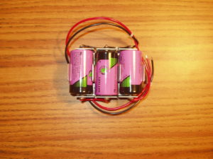
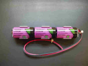
b. Long-Life Battery Pack (Rating: 7200 mAh), consisting of three 3.6V batteries, C-size, in series. See photos attached.
Tadiran Part # TL-2200/S. Newark Part # 00Z1076
Battery Pack, Approximate Life:
350-ohm bridge sensor: 120 hours.
1000-ohm bridge sensor: 150 hours.
IMPORTANT MESSAGE: These Lithium Ion batteries are classified as Hazardous Materials. As such, Binsfeld Engineering is not licensed to handle these batteries and we cannot process a customer purchase order for these batteries.
The Battery Holders can be purchased from McMASTER-CARR: http://www.mcmaster.com/#catalog/120/746/=qc2i6q
Part # 7712K721: Battery Holder, Aluminum, Side-By-Side for 3 C Cells.
Part # 7712K721
Part # 7712K871: Battery Holder, Aluminum, End-to-End for 3 C Cells.
Part # 7712K871
Note: The McMASTER-CARR Battery Holders do not include wiring. But the wiring will be simple for three batteries in series.
Any battery configuration that provides a 7.0V to 18.0V supply (9V typical) to the Transmitter can be used. You can bank batteries together to provide the voltage supply. BE CAREFUL about centrifugal force on the rotating shaft, especially when using larger, heavier batteries.
CAUTION: If you plan to use two 9V batteries in parallel, make sure the batteries are identical in name, construction and charge. If the charges are different, the weaker battery will act as a drain on the stronger battery and you will not get the expected 2x battery life. If the constructions of the two batteries in parallel are different, there is a serious risk of a bad chemical reaction, even risk of fire.
Generally, we do not recommend rechargeable batteries. For a 9V rechargeable battery, the operating life between recharges might be only 3-6 hours (200 mAh), compared to 24 hours life (1200 mAh) for a standard 9V Lithium battery. A standard 9V Alkaline battery, available at any general store, might have an operating life of 10 hours.
At least two customers have been successful using SOLAR FILM modules to power the Transmitter on the rotating shaft, eliminating the need for battery power. PowerFilm: http://www.powerfilmsolar.com/